Tuesday 26 November 2013

Creating a Time-Lapse Camera with the Raspberry Pi and Python

After the success using openCV with the Raspberry Pi camera to determine the positions of circles in an image, I thought it would be nice to explore more uses of the camera. My inspiration came from a chat with a consultancy I visited. They were in the middle of a large expansion of their site, and were having a lot of building work carried out. To document the building work they had set up a Raspberry Pi with a camera to capture the work and to create a time-lapse video of it.

How much fun does that sound?

My mind was made up - I decided to write a time-lapse video program using Python.

I knew taking the images would be quite simple, but the conversion into video would be more tricky.

My first thought was to make use of the openCV libraries again to turn the images into video. However while I believe this is possible, I really struggled to find the solution. Documentation for openCV is very much geared to C++ and not Python.

My second attempt was to use ffmpeg. Some googling had shown this was a nice solution for the conversion. However after installing and running it I got a message saying


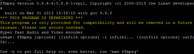
More googling told me I should install ffmpeg from binaries, which I am more than comfortable to do, but it does add complexity into my blog post...

Wait a minute! What was that last sentence on the error message? "Please use avconv instead"

More googling required!

It turns out that avconv does exactly what I need it to do. It converts a pile of images into a video. There are a lot of examples on the web explaining what settings you should use with avconv. However while the avconv website has a lot of information on there I found the best explanation came from the excellent Raspberry Pi Spy website, whose post was also explaining how to create a time-lapse video. Its worth having a look at his page, as he explains how to take images and create video using only the command line.

http://www.raspberrypi-spy.co.uk/2013/05/creating-timelapse-videos-with-the-raspberry-pi-camera/

Right so how do we write a Python program to create a time-lapse video?

The first thing you need to do is to install libav-tools.

Type the following into a command line.

sudo apt-get install -y libav-tools

Here is the full program, have a read through it and see if you can figure out what each line is doing. I will then explain each line in more detail.
import os
import time

FRAMES = 1000
FPS_IN = 10
FPS_OUT = 24
TIMEBETWEEN = 6
FILMLENGTH = float(FRAMES / FPS_IN)


frameCount = 0
while frameCount < FRAMES:
    imageNumber = str(frameCount).zfill(7)
    os.system("raspistill -o image%s.jpg"%(imageNumber))
    frameCount += 1
    time.sleep(TIMEBETWEEN - 6) #Takes roughly 6 seconds to take a picture

os.system("avconv -r %s -i image%s.jpg -r %s -vcodec libx264 -crf 20 -g 15 -vf crop=2592:1458,scale=1280:720 timelapse.mp4"%(FPS_IN,'%7d',FPS_OUT))

To begin with we need to import two libraries, os which will allow us to interact with the command line, and time to enable us to set the time between frames.

import os
import time

Now we will set some global variables. The nice thing about global variables is that you can change a variable that appears all through your program by just changing it in one location. Global variables also make your code more readable, as words explain what the variable is better than a number appearing thorughout your code. It also makes for code which is easier to modify as you know that all your global variables are specified at the top of your code.

We will set 5 global variables.

FRAMES = 1000
FPS_IN = 10
FPS_OUT = 24
TIMEBETWEEN = 6
FILMLENGTH = float(FRAMES / FPS_IN)

FRAMES sets the number of frames or images you will take and add to your video.
FPS_IN sets the number of the Frames Per Second (FPS) that go into the video. So if you want 10 of your frames to be used per second put the value to 10.
FPS_OUT sets the Frames Per Second of the video created. i.e. creates a video running at 24 Frames Per Second. If FPS_IN is less that FPS_OUT some FPS_IN frames will be used several times to bring the number up to FPS_OUT. Setting this value to 24 is a good value for digital video.
TIMEBETWEEN states the time (in seconds) between the frames that you are shooting with your camera. The Raspberry Pi camera takes roughly 6 seconds to take an image, so 6 seconds is the shortest time between shots.
FILMLENGTH works out how long your film will be in seconds. If you want to know this value, then you get your program to print it using the following line.

print FILMLENGTH

I am not going to print this out, but I do use it as a reminder of how long the film I am making will be.

Now we have set up all our variables we can get down to business. We want to take images every so often and save them as files. We will want to keep track of how many images we have taken so we know when to stop. So lets create a variable to do that.

frameCount = 0

The next thing we will do is enter a WHILE loop. A while loop keeps going WHILE something is true

while frameCount < FRAMES:

So while our number in frameCount is less than ( < ) the number we have stored in FRAMES we will run through the next 4 lines of code.

We will create a name for the pictures we want to save.

    imageNumber = str(frameCount).zfill(7)
The reason we want to do this is we want the files to be stored with incremental numbers. This line is quite clever (I think!)

It says we will create a variable called imageNumber. In that variable we will store a string of the value in frameCount. Remember a string is classed as text and not a number. Then using the .zfill(7) command we will ensure that the string has 7 digits by filling all preceding digits with a zero if there are not enough numbers. Some examples are:

'1' becomes '0000001'
'123456' becomes '0123456'

It's not a tool you use very often, but if you want something to be a certain amount of characters it's very useful!

Now we have the name of the image file we are going to create, lets take the image! We are going to use the line you can type into the shell command to take the image.

    os.system("raspistill -o image%s.jpg"%(imageNumber))

What does this line mean? Well the line for taking pictures with the Raspberry Pi camera and storing it as image.jpg is

raspistill -o image.jpg

but this needs to be typed into the command line. Well os.system allows you to access the command line.

You will notice there is a %s in there with %(imageNumber) after the text.

This says, take whatever is in the value imageNumber and put it in place of the %s. So if imageNumber was 0000001 our file would be called image0000001.jpg.

This is a great technique of easily modifying what is in a string.

As we want our number to increase each time we go through the while loop let us now increase frameCount.

    frameCount += 1

With imageNumber being made up of frameCount and some leading zeros, each time we run through the while loop we will get a different number as frameCount is increased each time.

Finally we want to be able to vary the time between taking each frame. This allows us to take our images a set distance apart. It takes roughly 6 seconds to take a picture with the Raspberry Pi camera.

    time.sleep(TIMEBETWEEN - 6) #Takes roughly 6 seconds to take a picture

Therefore the minimum time between each frame is 6 seconds. If we want the camera to wait 10 seconds per image, as it takes 6 seconds to take a picture we only want to sleep between frames for 4 seconds. Therefore we tell the program to sleep for a period of TIMEBETWEEN - 6.

This brings us to the last line of the code. As I mentioned earlier I found the Raspberry Pi Spy website to have the best details on how to use avconv. They suggest typing the following line into the command line to create video from the images. They also explain why.

avconv -r 10 -i image%4d.jpg -r 10 -vcodec libx264 -crf 20 -g 15 -vf crop=2592:1458,scale=1280:720 timelapse.mp4

I have modified this line slightly to make it a little more suitable for our program. I want to be able to set some of the variables using our global variables. Therefore I have changed the line slightly to this.
os.system("avconv -r %s -i image%s.jpg -r %s -vcodec libx264 -crf 20 -g 15 -vf crop=2592:1458,scale=1280:720 timelapse.mp4"%(FPS_IN,'%7d',FPS_OUT))
We already know why we use the os.system command, as this allows us access to the command line. I have also added in a few %s commands to switch in our global variables. This is using the same technique we used on the line where we took the picture. The difference is there are three variables we are switching in.

Let us look at he code inside the os.system brackets.

Most of the code is the same as from the Raspberry Pi Spy webpage, but there are a few differences.


  • -r %s this sets the frame rate for the number of our frames we want to use in the video per second. The %s calls the first item in the list %(FPS_IN,'%7d',FPS_OUT), which is FPS_IN, one of our global variables. 
  • -i image%s.jpg determines the name of the images we want to load into our video. Again we call something within our list  %(FPS_IN,'%7d',FPS_OUT), this time the second item. What does %7d do? Remember this is being run in the command line, so it's not a python command. The %7d iterates through 7 digit numbers. This is neat as we created our image files with 7 digit numbers. So it is iterating through the images we created. 
  • -r %s as for the first -r %s in this line this sets the number of FPS. However we call the FPS_OUT variable and insert this and not the FPS_IN variable. This will create a video of so many Frames Per Second depending on the value of FPS_OUT. If you are unsure 24 is a good default number to use.


All that is left now is to run your program. One word of warning is that avconv is not quick on the Raspberry Pi. 1000 Frames took 3.5 hours to turn into a video. However it's not a huge problem, you just leave it running over night!

I hope you found this tutorial interesting and I look forward to seeing some of your time-lapse videos!

Friday 1 November 2013

Python - Getting started with OpenCV

A couple of years ago a colleague of mine created a program to ensure that an item I had designed was calibrated properly. The program used a webcam to check a bracket was in the right position and reported back a pass or a fail. I did not know much about the workings of the program, other than it used something called a "Hough Transform". As a non-programmer at the time, I was impressed. I thought this was a very cool program.

A few weeks ago I needed to do something similar. I wanted to check that I could repeatedly position an item in the same location. My colleague has long left the company, so I thought it might be a good opportunity to see if I could write a similar program in Python. It was also an opportunity to finally put my Raspberry Pi camera module to good use.

If you don't have a Raspberry Pi camera, don't worry, you can test this out on pictures taken with a normal camera. I will also supply you some images later on for you to use. One of these I took with a camera phone, so you could do the same if you want to practice.

My starting point for this program was I knew that my colleague had used a Hough Transform, and that there were some good vision libraries available called openCV. I also knew these were available on Python. My program uses a Hough Circle Transform as opposed to a Hough Line Transform.

The objective I was trying to achieve was to be able to check the position of an item and to determine its offset in x, y and any rotation (theta) of the object.

I knew I was able to add some fiducial to the item, so opted for two circles. To make my circles a universal size, rather than drawing around coins to make my circles, I used the inside of a CD as a template. However I will show you how to tweak your program for other circles later!


The first thing you need to do it to install the openCv libraries onto your Raspberry Pi.

sudo apt-get install libopencv-dev python-opencv

To begin with I struggled to find information to get me started, and there seemed to be a lot of confusing information scattered about the web. What I did find out which makes things a little easier to understand is that openCV has released two types of Python interface called cv and cv2. If you are googling for further information it's worth keeping this in mind. We are going to use cv2 in this tutorial.

First of all here is my code and then we will analyse it line by line.

import os
import cv2
import math

##Resize with resize command
def resizeImage(img):
    dst = cv2.resize(img,None, fx=0.25, fy=0.25, interpolation = cv2.INTER_LINEAR)
    return dst

##Take image with Raspberry Pi camera
os.system("raspistill -o image.jpg")

##Load image
img = cv2.imread("/home/pi/Desktop/image.jpg") 
grey = cv2.imread("/home/pi/Desktop/image.jpg",0) #0 for grayscale

##Run Threshold on image to make it black and white
ret, thresh = cv2.threshold(grey,50,255,cv2.THRESH_BINARY)

##Use houghcircles to determine centre of circle
circles = cv2.HoughCircles(thresh,cv2.cv.CV_HOUGH_GRADIENT,1,75,param1=50,param2=13,minRadius=0,maxRadius=175)
for i in circles[0,:]:
    #draw the outer circle
    cv2.circle(img,(i[0],i[1]),i[2],(0,255,0),2)
    #draw the centre of the circle
    cv2.circle(img,(i[0],i[1]),2,(0,0,255),3)

##Determine co-ordinates for centre of circle
x1 = circles[0][0][0]
y1 = circles[0][0][1]
x2 = circles[0][1][0]
y2 = circles[0][1][1]
##Angle betwen two circles
theta = math.degrees(math.atan((y2-y1)/(x2-x1)))

##print information
print "x1 = ",x1
print "y1 = ",y1
print "x2 = ",x2
print "y2 = ",y2
print theta
print circles

##Resize image
img = resizeImage(img)
thresh = resizeImage(thresh)
##Show Images 
cv2.imshow("thresh",thresh)
cv2.imshow("img",img)

cv2.waitKey(0)

First we import 3 modules - os, cv2 and math.
import os
import cv2
import math

Now we create a function to resize images. Although we do our analysis on the full image, we will make the images smaller before we display them on the screen.

##Resize with resize command
def resizeImage(img):
    dst = cv2.resize(img,None, fx=0.25, fy=0.25, interpolation = cv2.INTER_LINEAR)
    return dst

There is a more in-depth explanation of the resize function on the geometric image transformations help page in the openCV documentation.

http://docs.opencv.org/modules/imgproc/doc/geometric_transformations.html

However the important things to note are:
  • img is the image we want to resize.
  • fx=0.25 and fy=0.25 are the factors that x and y are multiplied by. 0.25 makes the image 1/4 size.

Next we take an image using the Raspberry Pi camera.

##Take image with Raspberry Pi camera
os.system("raspistill -o image.jpg")

os.system allows us to input a command into the command line. We know from the camera documentation that "raspistill -o image.jpg" will take an image with the camera and store it as image.jpg.

Now we load the image twice into our program. The first time as a colour image, the second as a grey-scale image.

##Load image
img = cv2.imread("/home/pi/Desktop/image.jpg") 
grey = cv2.imread("/home/pi/Desktop/image.jpg",0) #0 for grayscale

We then use cv2.threshold to turn our image into black and white.

##Run Threshold on image to make it black and white
ret, thresh = cv2.threshold(grey,50,255,cv2.THRESH_BINARY)

There is more information about the threshold function on the transformations help page on the openCV documentation.

http://docs.opencv.org/modules/imgproc/doc/miscellaneous_transformations.html

The important parts of the code are:
  • grey - the image we are converting.
  • 50 - is the threshold value. This is between 0 and 255. 0 is white and 255 is black. You may need to modify this value depending on your lighting conditions.
  • 255 - If a pixel is above the threshold value, in our case 50, we will make it 255 (black). Else is it 0 (white)
On this black and white image we now run hough circles.

This line in the code carries out the HoughCircle transform. This is the most important line in the code, and the one you are most likely to have to modify to suit your image.

##Use houghcircles to determine centre of circle
circles = cv2.HoughCircles(thresh,cv2.cv.CV_HOUGH_GRADIENT,1,75,param1=50,param2=13,minRadius=0,maxRadius=175)

  • thresh - refers to the fact we are carrying out the hough transform on the black and white image.
  • 75 - refers to the minimum distance allowed between circles. If you are getting too many circles close together you may want to increase this and vice versa.
  • Param1 = 50. This is one of the parameters which determines where the circles are, you can play around with this figure if needs be.
  • Param2 = 13. This is the more important of the parameters. If you are getting too many circles then increase this number, and vice versa. Small changes to this make large differences!
  • minRadius - the smallest radius allowed for a circle.
  • MaxRadius - the largest radius allowed for a circle.

HoughCircle returns a x and y co-ordinate for each circle. It also returns a radius. We are storing these values in the variable called circles.

Again there is more information available about HoughCircle on the function detection page of the openCV documentation under HoughCircles.

http://docs.opencv.org/modules/imgproc/doc/feature_detection.html

We now go through each of these circles in order. For each of the circles we draw its circumference and its centre onto the coloured image we stored in the variable img.

for i in circles[0,:]:
    #draw the outer circle
    cv2.circle(img,(i[0],i[1]),i[2],(0,255,0),2)
    #draw the centre of the circle
    cv2.circle(img,(i[0],i[1]),2,(0,0,255),3)

More information on the circle command is seen on the OpenCV docs page which covers drawing functions.

http://docs.opencv.org/modules/core/doc/drawing_functions.html

Now as I stated at the start of this blog there was an actual reason for writing this program. I wanted to be able to log the x and y co-ordinates of the circles to see how they varied when putting in different items. I also wanted to work out the angle between the circles, and see how that varied.

The next lines of code separate out the x and y co-ordinates. They also work out the angle between them using simple trigonometry.

##Determine co-ordinates for centre of circle
x1 = circles[0][0][0]
y1 = circles[0][0][1]
x2 = circles[0][1][0]
y2 = circles[0][1][1]
##Angle betwen two circles
theta = math.degrees(math.atan((y2-y1)/(x2-x1)))

Finally to display the images nicely on the Raspberry Pi I pass each image through the function to resize them...

##Resize image
img = resizeImage(img)
thresh = resizeImage(thresh)

...then I display the images.

##Show Images 
cv2.imshow("thresh",thresh)
cv2.imshow("img",img)

There is no need to display the images if you don't want to. However I think its good to see what the thresh image and the final image looks like. These are good to help any fault finding. 

You also need the next line for the code to work.

cv2.waitKey(0)

Here is a link to the code, so you can download it rather than type it.


If you don't have a Raspberry Pi Camera there are a few images below which you can use to test your code on. Just change the code to comment out the line about taking the image with the camera, and change the name of the files you are opening to suit.

The first one is taken using my Raspberry Pi camera.

Hough_image1.jpg

The second is from my phone.

Hough_image2.jpg

If you have any problems with the code, try it on these two images first, as I know these work. I think most problems you will have will be to do with lighting. There was a fair amount of playing around with certain parameters, particularly param2 to get this to work.

Keep an eye on my blog, as there could well be some more openCV programs at some point!